Congratulations to the team for completing a successful Conceptual Design Review of the Eviation Alice production configuration!
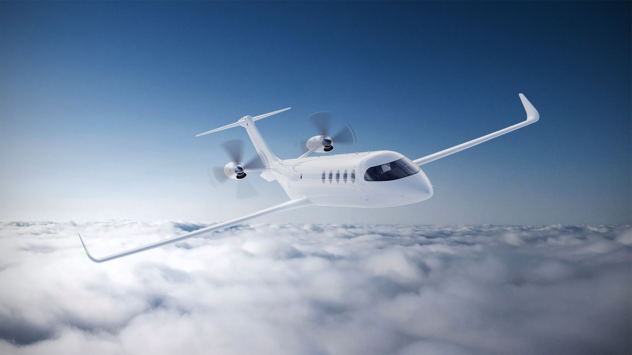
This Conceptual Design Review (CoDR) represents a significant milestone for Eviation’s all-electric eCTOL design introducing features that improve performance, reduce complexity, retire technical risk, and ensure robustness to evolving battery technology. The goal of this effort was to evolve the flight prototype design into a compelling commercial product while ensuring a smooth path to certification.
TLG’s multidisciplinary team was led by Chief Aerodynamicist Andrew McComas and Flight Analyst DER Reid McCaul with support from a talented team of engineers at TLG Aerospace, Eviation, and key suppliers. Many thanks to our counterparts at Eviation for allowing us the opportunity to contribute to this great product!
The article below is reposted courtesy of Eviation.
Eviation Completes Conceptual Design Review of Alice Aircraft
- Eviation has completed the Conceptual Design Review of the all-electric Alice aircraft
- The review is a significant milestone toward certification and commercialization of Alice
- Production Aircraft design of Alice optimized for certification, streamlined manufacturing, and to provide a best-in-class passenger experience
ARLINGTON, Wa., U.S., January 25, 2024 – Eviation Aircraft, a manufacturer of all-electric aircraft, today announced that it has completed the Conceptual Design Review (CoDR) of the Alice aircraft. The review is a significant milestone, assuring a configuration that is both certifiable and enables streamlined manufacturing. It maintains Alice’s signature look, while optimizing performance, and further enhancing its unmatched cabin experience.
The CoDR, conducted with the support of TLG Aerospace, built on the extensive data gathered from Alice’s pioneering 2022 flight, wind tunnel testing recently completed at the Kirsten Wind Tunnel in Seattle, feedback from Eviation’s customer advisory board, and months of engineering work.
Features introduced in the Production Aircraft design include:
- a constant cross-section that reduces Alice’s part count and manufacturing costs, while also enabling future variants of the aircraft
- structural segments designed for field re-assembly with standard tooling available to Maintenance, Repair and Overhaul (MRO) services
- a larger, centralized Energy Storage System (ESS) compartment above the wing that can integrate a range of ESS solutions now and in the future, in addition to streamlining certification
- optimized cabin space allowing for a side-mounted carry-on stowage compartment unique in the commuter class
Creating the Future of Flight
With orders totaling more than US$ 5 billion, the all-electric Alice is pioneering a new era of sustainable air travel. Alice’s 9-seat commuter and cargo versions are designed to delight customers and passengers with innovative technology and beautiful design, while also providing carbon-free, cost-effective, and convenient point-to-point travel.
“Completing the Conceptual Design Review is a major step in Alice’s journey, moving us significantly closer to aircraft certification and Entry Into Service,” said Andre Stein, CEO of Eviation. “The latest refinements have further enhanced the exceptional design of Alice, which has received orders from operators around the world keen to decarbonize their fleets. This is an exciting year for Eviation, as Alice makes tremendous strides toward making the electric aviation revolution a commercial reality.”
About Eviation Aircraft
Based in Washington State, Eviation Aircraft Inc. develops and manufactures electric aircraft to delight operators and passengers with green, cost efficient, and convenient regional transportation. Its electric propulsion units, high-energy-density batteries, mission-driven energy management, and innovative airframe are designed from the ground up for electric flight. Please visit us at www.eviation.com.
Contact
media@eviation.com
About TLG Aerospace
TLG is an aerospace engineering services company that specializes in full vehicle analysis and optimization including static and dynamic loads, flutter, stability and control, aerodynamic design, Computational Fluid Dynamics (CFD) analysis, airframe stress analysis and design, FAA certification and aircraft performance and handling qualities. Our engineers have experience with over 100 aircraft models from more than 40 different manufacturers. www.tlgaerospace.com
TLG Aerospace will be at Xponential April 22nd and 23rd
Catch up with TLG’s Business Development Director, Tommy Gantz, at AUVSI — Association for Uncrewed Vehicle Systems International‘s Xponential show in San Diego. She will be attending on April 22nd and 23rd and would love to share how TLG Aerospace’s full suite of engineering services can best serve your projects. Email her here or reach out on LinkedIn.
Have a great show!
Catch up with TLG’s Business Development Director, Tommy Gantz, at AUVSI — Association for Uncrewed Vehicle Systems International‘s Xponential show in San Diego. She will be attending on April 22nd and 23rd and would love to share how TLG Aerospace’s full suite of engineering services can best serve your projects. Email her here or reach out on LinkedIn.
Have a great show! #XPO24
TLG Aerospace will be at the Aerospace & Defense Supplier Summit March 12-14th in Seattle, WA

TLG is sending a great crew to A&DSS beginning Tuesday, next week in Seattle, WA. If you didn’t get a chance to schedule your B2B meeting with us, we can still connect and support your aircraft design and certification projects with our full suite of engineering services from concept through certification. Email our director of business development, Tommy Gantz, here.
Tommy will be attending all three days accompanied by structural and design engineers Frans Sell and Tim Moloney respectively. Frans will attend on the 13th and Tim on the 14th.
We look forward to seeing you at the show!
TLG will be at HAI’s HELI-EXPO 2024
TLG’s Business Development Director, Tommy Gantz, is looking forward to seeing you next week on Tuesday and Wednesday (February 27th and 28th) at Helicopter Association International‘s HELI-EXPO 2024.
Reach out anytime now through her time at the show to schedule a meeting to discuss how our full suite of engineering services can benefit your modification projects.
TLG serves customers around the world from concept through certification with five independent FAA DERs on our team. We have worked on a variety of new electric programs including electric aircraft and eVTOLs.
If you’re missing the show and would still like to explore working with TLG, please don’t hesitate to reach out to Tommy to arrange a meeting with our team. Have a great show!
TLG will be attending PNAA Advance 2024

You can catch Tommy Gantz and Christy Fields at the Lynnwood Events Center, this February 5-8th.
Please email Tommy or DM us on LinkedIn to schedule a meeting. We look forward to seeing you at this year’s event and supporting your aircraft design, modification, and certification projects!
TLG Aerospace is Your Trusted Partner for CFD Services
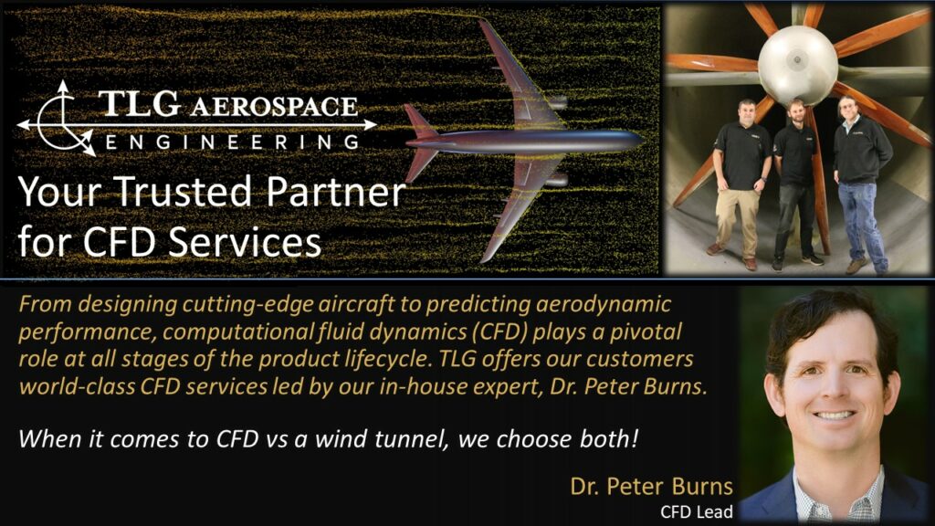
From designing cutting-edge aircraft to predicting aerodynamic performance, computational fluid dynamics (CFD) plays a pivotal role at all stages of the product lifecycle.
Since we were just in the wind tunnel last month (see our post here), we thought it would be fun to discuss how CFD can be used as a virtual wind tunnel. We’re big fans of real-world testing, but we think you get more value when you combine it with CFD-based predictions.
Below are a few of the advantages CFD has over a wind tunnel which make it a complementary tool.
◾ Upfront costs and schedule – Wind tunnel models are expensive and take time to build. These costs pay off once you are in the tunnel, but CFD has a much lower cost and lead time to seeing the first actionable results. Further, CFD allows teams to refine their early-stage concepts quickly, which means a design is much more mature by the time you enter the tunnel.
◾ Maximizing value – During a wind tunnel test campaign, time is a limited resource, and you want to extract the most value you can. Having a good set of CFD-based predictions allows the test engineers to focus on key strategic objectives or to troubleshoot unexpected results. One example is simulating full-scale Reynolds numbers in a low-speed (non-pressurized) tunnel. Full and model-scale CFD results can help the test crew employ techniques to approximate full-scale results.
While software and cloud computing have come a long way, you still need a team that knows how to interpret and deliver actionable results. TLG offers our customers world-class CFD services led by our in-house expert Dr. Peter Burns. Before joining TLG, Peter was the global aerospace technical specialist for Siemens PLM Software supporting their STAR-CCM+ software. Check out Peter and the rest of our leadership team, as well as a complete look at our engineering service offering, at https://lnkd.in/g9i2jwQ7.
To learn more about the CFD capabilities at TLG, check out the links below.
◾ AWS webinar in partnership with Siemens – https://lnkd.in/g5rj2veX
◾ TLG was one of the earliest AWS HPC partners, just check out this case study from 2016! Quite a bit has changed since then, but it is an interesting look back – https://lnkd.in/gvmvhk6Z
Save the Date – Aircraft Structural Loads: Criteria, Analysis, and Validation Course Led by TLG’s Dr. Josh Dementi in Seattle, WA.
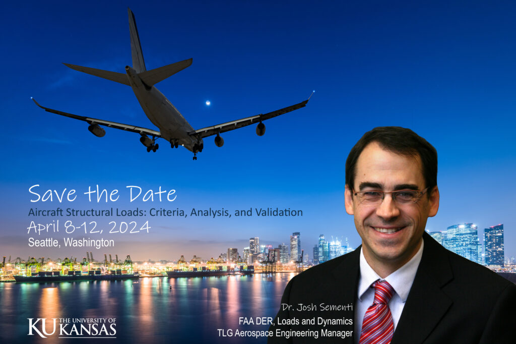
Did you know one of TLG’s esteemed engineering managers also leads a course in aircraft structural external loads through The University of Kansas? Dr. Josh Sementi is overflowing with knowledge in the area.
In addition to engineering manager with responsibilities for loads, dynamics, and flutter, Josh is also an independent consultant FAA Loads DER with full approval authority for both 14 CFR Parts 23 and 25 airplanes and is an alumnus of the University of Washington where he earned his Doctor of Science degree in aerospace engineering. In the past, he has taught courses at Seattle U and for the UW Grad program.
A long-time colleague and friend to TLG team members, Josh joined TLG from Aviation Partners Boeing where he led the loads and dynamics engineering department in support of Supplemental Type Certificates for winglet installations on Boeing 737 Next Generation, 757, and 767 transport aircraft; and Dassault Falcon 2000 business jets. This experience includes both performing and directing MSC; Nastran aeroelastic analyses, with extensive use of Matlab tools for additional analysis and data processing.
Josh recently wrapped teaching The University of Kansas’ high-level survey course offered annually, which helps give perspective on aircraft structural external loads analysis (including criteria, design, analysis, fatigue, certification, validation, and testing) to regulators, flight test engineers, flutter, and aerodynamics disciplinaries, and more. The transfer of knowledge from Josh and the course content helps participants stay engaged with loads and how to best utilize loads outputs and ask the right questions as to what needs to be done.
The traveling course was held in San Diego in 2023 and will take place here in Seattle this year. Please Save the Date to get expert insight from Dr. Sementi, April 8-12, 2024, at the DoubleTree Suites by Hilton Hotel Seattle Airport Southcenter.
Learn more about the course here.
We feel lucky to have Josh as part of the TLG Aerospace team.
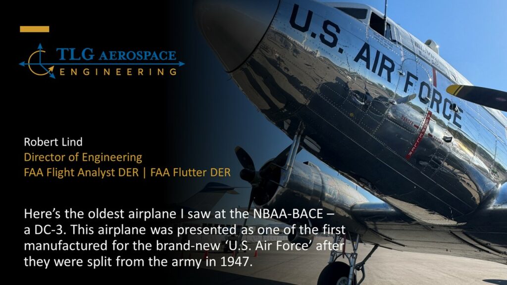
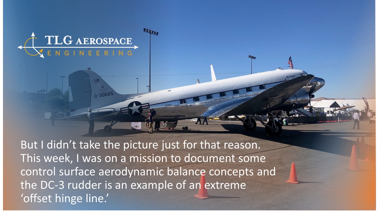
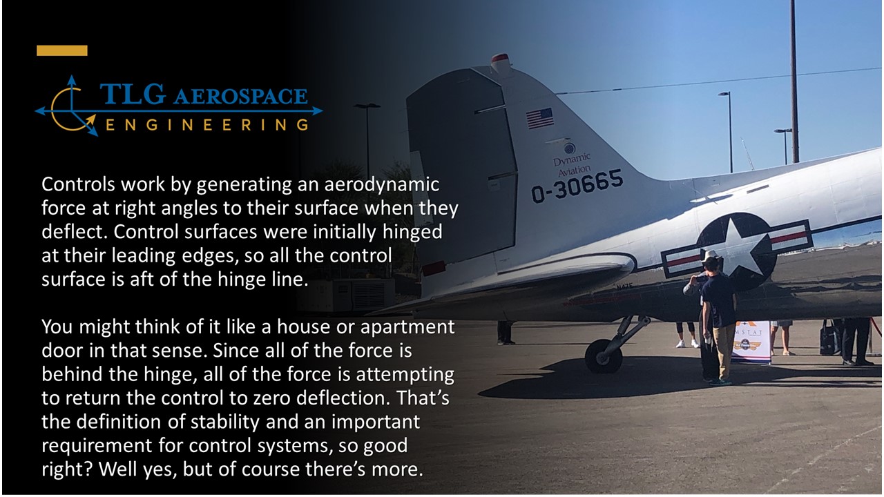
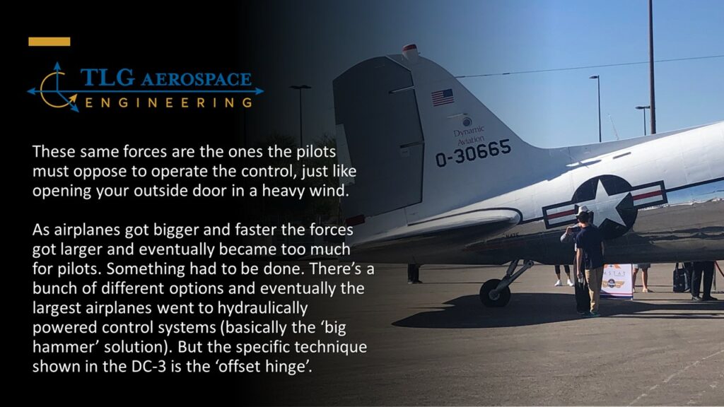
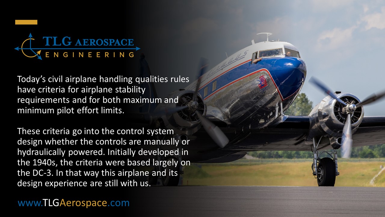
Extreme Offset Hinge Line on the DC-3 Rudder
TLG had a great time at #NBAABACE 2023 meeting with our customers and friends, and forming new relationships. We look forward to following up.
One of the highlights of the annual show is visiting the flight line with Robert Lind as there are so many exciting parts and functions of aircraft to learn with an expert at your side. Tommy Gantz and Christy Fields were thankful to share Robert’s excitement and learn more great facts from him during our last day at the show.
Below, Robert summarizes his mission to document some control surface aerodynamic balance concepts at the aircraft display. The DC-3 rudder is an example of an extreme ‘offset hinge line.’ Read on for more from Robert . . .
TLG is a proud Sponsor of this year’s AFA Summit
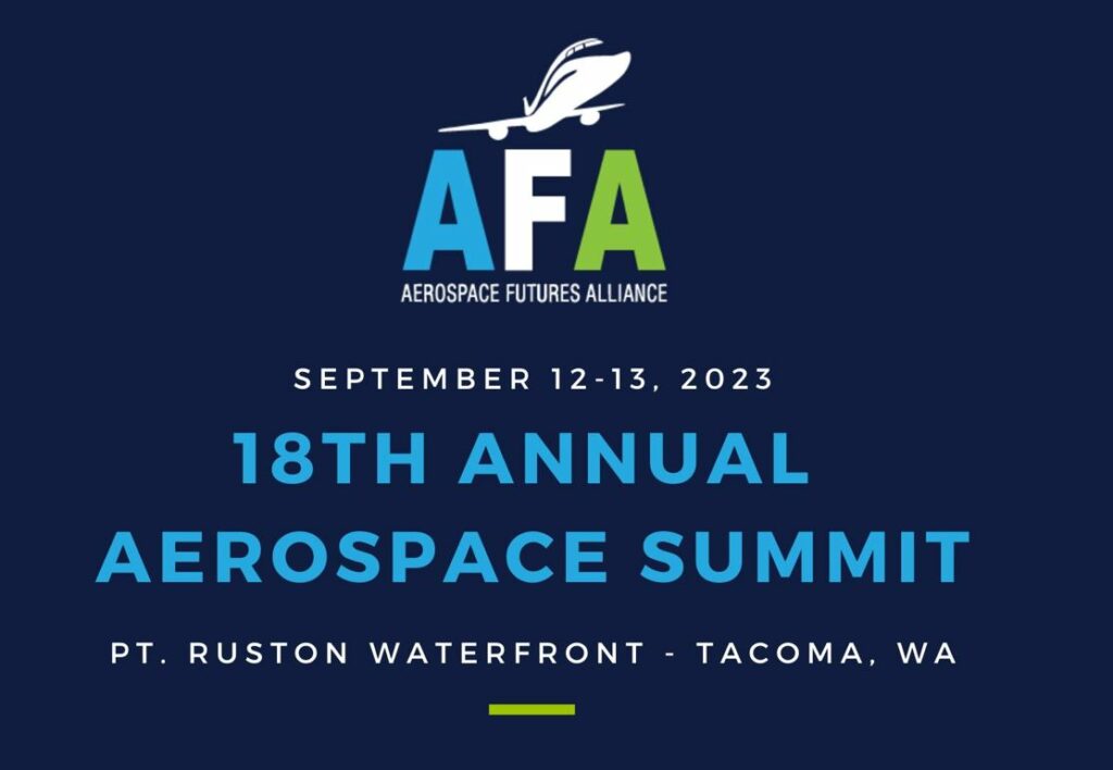
TLG is again a proud sponsor of Aerospace Futures Alliance’s 18th Annual Aerospace Summit to be held at Pt. Ruston.
This conference brings together the top thought leaders in Washington’s aerospace industry to discuss the most pressing issues facing our industry and share solutions with our federal and state elected officials. Speakers will be announced closer to the event.
Steve Muenzberg and Lynnette Muenzberg, who is also AFA’s BoD President, look forward to joining this event. Please join TLG on the 12th and 13th for a great day of discussion!
Planning to stay at beautiful Pt. Ruston during the Summit? Book your room with AFA’s special event rate.
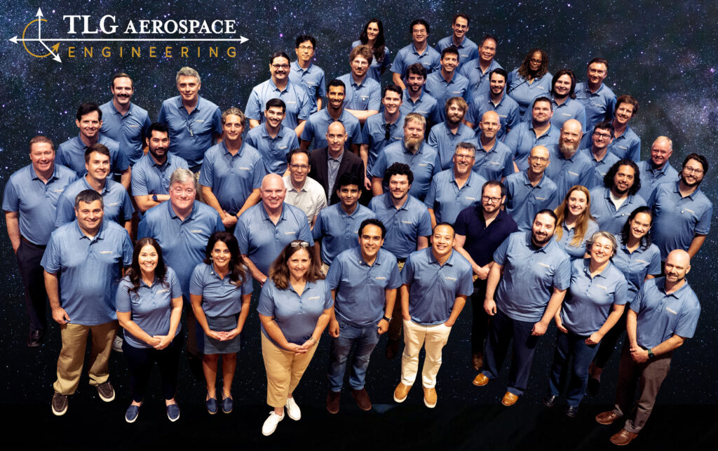
TLG Aerospace Celebrates 15 Years of Engineering Excellence
SEATTLE – “Build it and they will come” is a philosophy based on the idea that if you create something great, people will naturally gravitate to wanting to be part of it. TLG Aerospace started with a great idea and then it evolved into reality with its first projects and keys to office space on Seattle’s Lake Union in July of 2008.
Last week, TLG Aerospace gathered to celebrate 15 years in business as a proud member of the aerospace industry, one of the most innovative and dynamic sectors in the world.
Last week, TLG Aerospace gathered to celebrate 15 years in business as a proud member of the aerospace industry, one of the most innovative and dynamic sectors in the world. For its founders, launching a dream place to work while remaining a recognized leader in providing engineering excellence to TLG’s partners for a decade and a half has been an exciting journey requiring vision, passion, and perseverance. Consistent reliability and innovation have also required great leadership, hard work, creativity, and collaboration. Behind the exciting projects TLG is a part of is a great team of people.
Better Together
“After 15 years, TLG Aerospace continues to be an engineer’s paradise with projects running the gamut of the aerospace industry. TLG engineers are working at the forefront to shape novel configurations and ensure their safety in operation. I can’t imagine a better place to work if you’re an engineer who wants to help solve the industry’s most challenging problems.” Says Engineering Manager Allen Foulstone, who recently celebrated 10 years with TLG.
TLG is at the forefront of working on exciting innovative projects from developing the largest aircraft in the world and designing the next generation of hypersonic vehicles to helping fight fires working on some of the largest aerial platforms to moving packages and people around the world and launching tourism to space.
“The flight hardware I develop makes shipping logistics better, retrofits airplanes for new roles and missions, and will take us to the moon and beyond,” says Miguel Ibarra, our three-year stress and design team member.
Green Aviation Solutions
TLG’s work has helped save 14 billion gallons of fuel, adding the most effective winglets to several platforms in collaboration with industry leading companies including Aviation Partners which has transformed aviation for more than 25 years with their performance-driven, fuel-saving advanced winglet technology.
And TLG’s clean energy solutions don’t stop there, as the company has been part of more than a half-dozen electric vertical takeoff and landing (eVTOL) projects and is providing a host of engineering support, including design and configuration for Eviation’s Alice all-electric commuter aircraft.
“What an exciting day it was to be onsite for the first all-electric test flight which was celebrated around the globe.” says Andrew McComas, Aerodynamicist, Engineering Manager, and another 10-year veteran of TLG.
TLG is honored to be part of this amazing industry and the company is grateful to its customers, partners, suppliers, and employees for their trust and support throughout the years. TLG is proud of its achievements and contributions to the aerospace community and is excited about the future opportunities that lie ahead for TLG and for the industry.
Closing words from Director of Engineering Robert Lind, who was the first hired TLG employee: “I’m honored to be a part of TLG’s 15 years in business. From the very first day with three individuals to today with 70-plus engineers, our focus has been to support our customers with a team of talented engineers and staff. We’ve built core capabilities in the flight sciences, aerospace design, and structural analysis and combined them with outstanding airworthiness certification and program management capabilities. The resulting team has supported an astonishing array of programs — from the largest airplanes flying to hand-launched gliders, from space access to ground transportation, power generation, and more. We succeed by helping our customers solve their problems and move forward with their programs.
“As a young engineer, I quickly realized the kind of programs I wanted to be part of require a talented team working together. Programs requiring not just my skills, perspective, and time, but also those of others. Here at TLG, I am part of a strong, diverse, and capable team that does amazing work each day. For 15 years, it’s been a pleasure to work with this group and their ever-growing capabilities. I look forward to many more years to come.”
About TLG Aerospace
TLG is an aerospace engineering services company that specializes in full vehicle analysis and optimization including static and dynamic loads, flutter, stability and control, aerodynamic design, Computational Fluid Dynamics (CFD) analysis, airframe stress analysis and design, FAA certification and aircraft performance and handling qualities. Our engineers have experience with over 100 aircraft models from more than 40 different manufacturers. www.tlgaerospace.com